Solar Panel Wiring Guide ⎻ Comprehensive Plan (as of 01/27/2026)
This comprehensive guide‚ updated as of today’s date‚ details solar system wiring‚ diagrams‚ safety‚ and configurations for optimal performance and code compliance.
Solar panel wiring is the crucial process of connecting photovoltaic (PV) modules to create a functional solar power system. It’s more than just connecting wires; it’s about understanding how each component – panels‚ inverters‚ charge controllers‚ and batteries – interacts to efficiently harness solar energy. A well-designed wiring scheme maximizes energy production‚ ensures system safety‚ and complies with local electrical codes.
Creating a solar wiring diagram is the first step‚ acting as a blueprint for the entire installation. These diagrams illustrate the interconnection of all system components‚ ensuring a clear and organized approach. Whether you’re building a grid-tied system to offset electricity bills or an off-grid setup for energy independence‚ proper wiring is paramount. This guide will navigate you through the essential aspects‚ from understanding wiring configurations to avoiding common mistakes‚ empowering you to design and implement a reliable solar power solution.
Understanding Solar Wiring Diagrams

Solar wiring diagrams are essential blueprints for any photovoltaic (PV) system installation‚ visually representing the interconnectedness of all components. They detail how solar panels‚ inverters‚ charge controllers‚ batteries‚ and the electrical panel are linked‚ ensuring a safe and efficient energy flow. Understanding these diagrams is critical for both installers and homeowners.
A typical diagram uses standardized symbols to represent each component‚ clarifying the wiring configuration. Key elements include positive and negative terminals‚ wire gauges‚ and fuse/breaker locations. Diagrams differentiate between grid-tied and off-grid systems‚ reflecting their unique wiring requirements. Learning to interpret these diagrams allows for accurate system design‚ troubleshooting‚ and maintenance. Online tools‚ like Solar Design Labs‚ simplify diagram creation‚ while readily available resources offer pre-designed layouts for common system configurations.
Essential Components for Solar Panel Wiring
Successful solar panel wiring relies on several key components working in harmony. First‚ Solar Panels (PV Modules) capture sunlight and convert it into DC electricity. Inverters‚ either grid-tied or off-grid‚ transform this DC power into usable AC electricity for homes or the grid.

For off-grid systems‚ Charge Controllers regulate the voltage from the panels to safely charge Batteries‚ storing energy for later use. Proper wire sizing‚ fuses‚ and disconnect switches are also crucial for safety and system protection. Selecting high-quality components compatible with your system’s voltage and current requirements is paramount. Understanding the specifications of each component ensures optimal performance and longevity of your solar installation.
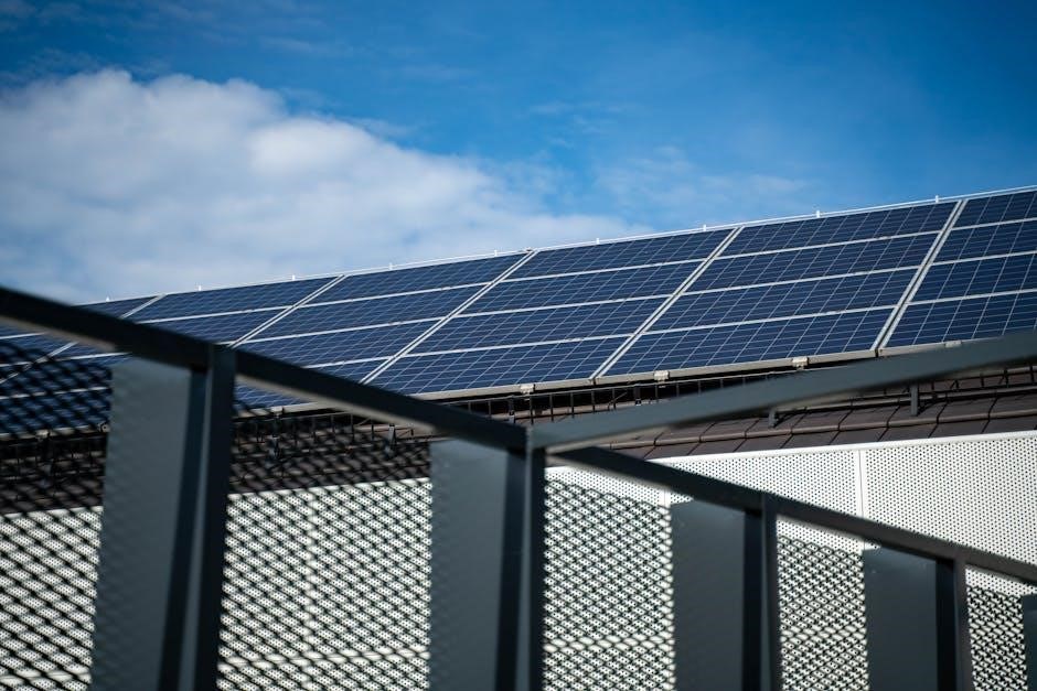
Solar Panels (PV Modules)
Solar panels‚ also known as photovoltaic (PV) modules‚ are the fundamental building blocks of any solar energy system. These panels consist of numerous solar cells that convert sunlight directly into direct current (DC) electricity. Panel wattage varies‚ influencing system size and output.
When selecting panels‚ consider factors like efficiency‚ temperature coefficient‚ and warranty. Understanding voltage and current ratings is crucial for proper wiring configurations. Stringing panels together – connecting them in series or parallel – impacts overall system voltage and amperage. Renogy panels‚ for example‚ are designed for straightforward connections. Proper panel mounting and orientation maximize sunlight capture‚ optimizing energy production. Careful consideration of these factors ensures efficient and reliable solar power generation.
Inverters (Grid-Tied & Off-Grid)
Inverters are essential components that convert the DC electricity generated by solar panels into alternating current (AC) electricity‚ which is used by most homes and businesses. There are two primary types: grid-tied and off-grid inverters. Grid-tied inverters synchronize with the utility grid‚ allowing excess power to be sent back for credit (net metering).
Off-grid inverters‚ used in independent systems‚ create a stable AC source without grid connection. Selecting the right inverter depends on your system’s design and energy needs. Wiring an inverter requires careful attention to voltage and current compatibility. Proper grounding is critical for safety. Understanding inverter specifications and following manufacturer guidelines ensures efficient and safe operation‚ maximizing the benefits of your solar installation.
Charge Controllers (For Off-Grid Systems)
Charge controllers are vital for off-grid solar systems‚ regulating the voltage and current flowing from the solar panels to the batteries. They prevent overcharging‚ which can damage batteries and reduce their lifespan‚ and also protect against reverse current flow at night. Two main types exist: Pulse Width Modulation (PWM) and Maximum Power Point Tracking (MPPT).
MPPT controllers are more efficient‚ especially in colder climates‚ by optimizing power transfer. Proper wiring of the charge controller is crucial‚ ensuring correct polarity and wire gauge. Selecting a controller with sufficient amperage capacity for your solar array is essential. Following the manufacturer’s instructions guarantees optimal battery health and system performance in off-grid applications.
Batteries (For Off-Grid Systems)
Batteries are the energy storage component in off-grid solar setups‚ accumulating power generated by the panels for use when sunlight isn’t available. Common battery types include lead-acid (flooded‚ AGM‚ gel) and lithium-ion. Lithium-ion batteries offer higher energy density‚ longer lifespan‚ and better discharge rates‚ but come at a higher cost.

Proper battery sizing is critical‚ based on energy consumption and desired autonomy. Wiring batteries in series increases voltage‚ while parallel connections increase capacity. Safety precautions are paramount‚ including adequate ventilation for lead-acid batteries and using appropriate fuses. Regular maintenance and monitoring ensure optimal performance and longevity of your battery bank.
Safety Precautions for Solar Panel Wiring
Working with solar panel wiring involves electrical hazards; prioritizing safety is crucial. Always disconnect the solar panels and any connected electrical sources before commencing work. Utilize properly insulated tools and wear appropriate personal protective equipment (PPE)‚ including gloves and safety glasses.
Understand DC voltage is significantly different than AC and can be dangerous. Ensure all connections are secure and weatherproof to prevent shorts and corrosion. Adhere strictly to local electrical codes and regulations. If unfamiliar with electrical work‚ consult a qualified professional. Never work alone and always have a clear understanding of the system before beginning any wiring tasks.
Wiring Configurations: Series vs. Parallel
Solar panel wiring utilizes series‚ parallel‚ or a combination of both configurations to achieve desired voltage and current levels. Series wiring increases voltage while maintaining current‚ connecting positive to negative of subsequent panels. This is ideal for higher voltage applications‚ but shading one panel impacts the entire string.
Parallel wiring maintains voltage while increasing current‚ connecting positive to positive and negative to negative. It’s more tolerant of shading‚ but requires larger wire gauges. Series-parallel combines benefits‚ creating multiple series strings wired in parallel‚ offering both higher voltage and current‚ and improved shading tolerance. Careful planning is essential for optimal system performance.

Series Wiring: Advantages & Disadvantages
Series wiring connects solar panels positive to negative‚ increasing the overall system voltage while the current remains constant. A key advantage is reduced wire size and cost due to lower current‚ making it efficient for long distances. It’s well-suited for grid-tied inverters requiring higher DC voltage.
However‚ series wiring has significant disadvantages. Shading on even one panel drastically reduces the output of the entire string‚ creating a bottleneck. A single panel failure can disable the whole series. Temperature variations between panels can also impact performance. Careful panel selection and placement are crucial for mitigating these drawbacks.
Parallel Wiring: Advantages & Disadvantages
Parallel wiring connects all positive terminals together and all negative terminals together‚ increasing the overall system current while maintaining the voltage of a single panel. A major advantage is improved shading tolerance; if one panel is shaded‚ the others continue to produce power at their maximum capacity. Individual panel failures don’t shut down the entire system‚ enhancing reliability.
However‚ parallel wiring has drawbacks. It requires larger gauge wires to handle the increased current‚ raising material costs. Potential for circulating currents exists if panels aren’t perfectly matched‚ requiring blocking diodes. It may be less efficient for long-distance transmission due to higher current losses.
Series-Parallel Wiring: Combining the Best of Both Worlds
Series-parallel wiring strategically combines the benefits of both series and parallel configurations. First‚ panels are connected in series to achieve a higher voltage‚ then these series “strings” are connected in parallel. This approach offers increased current and improved shading tolerance compared to purely series wiring.
It’s particularly useful for larger systems where higher voltage is needed for efficient transmission and inverters. The system is more resilient to individual panel failures than a series configuration‚ but less so than a purely parallel setup. Careful planning is crucial to balance string lengths and ensure optimal performance. Properly designed series-parallel systems maximize energy harvest and system reliability.
Designing Your Solar Panel Wiring Layout
Effective solar panel wiring layout design is crucial for maximizing energy production and ensuring system safety. Begin by assessing your site’s shading patterns and roof orientation to optimize panel placement. Consider the inverter’s voltage and current limitations when determining string sizes – series and parallel configurations impact these parameters.
Minimize wire lengths to reduce voltage drop and energy loss. Plan for easy access for maintenance and troubleshooting. Utilize wiring diagrams to visualize the layout before installation. Adhering to local electrical codes is paramount. A well-planned layout streamlines installation‚ enhances performance‚ and ensures long-term system reliability. Proper design prevents potential hazards and maximizes your investment.

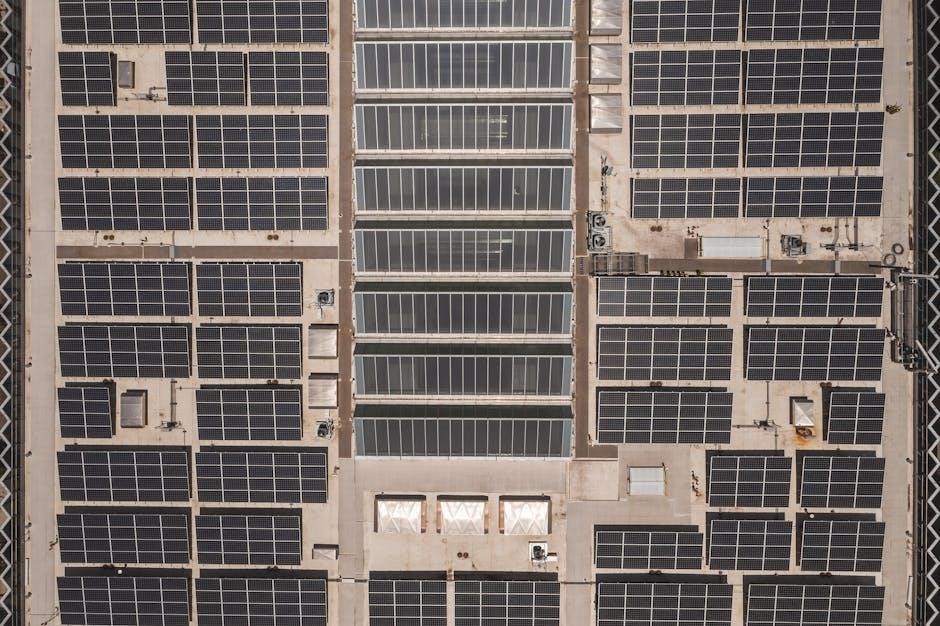
Grid-Tied System Wiring Diagrams
Grid-tied systems connect to the utility grid‚ enabling net metering and power export. Typical diagrams illustrate solar panels connected in series to form strings‚ then wired to a central inverter. The inverter converts DC power to AC power‚ synchronized with the grid. A dedicated circuit breaker and disconnect switch are essential for safety and maintenance.
Diagrams showcase the AC output connecting to the electrical panel‚ often through a dedicated breaker. Monitoring systems are frequently integrated‚ providing performance data. Compliance with utility interconnection standards is vital. These diagrams emphasize safety features like grounding and overcurrent protection. Understanding these diagrams is key for installers and homeowners‚ ensuring a secure and efficient grid-tied solar installation.
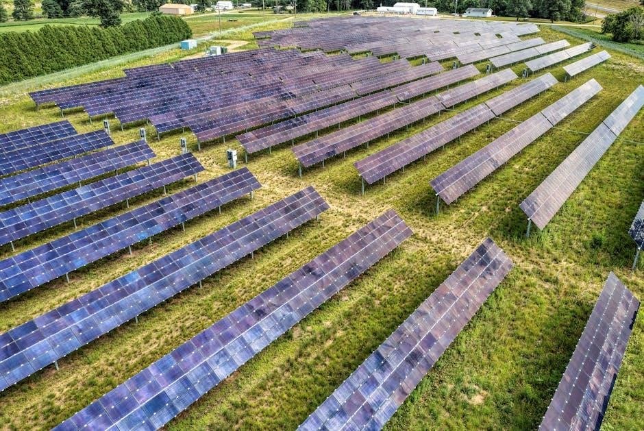
Off-Grid System Wiring Diagrams
Off-grid systems operate independently of the utility grid‚ requiring energy storage. Diagrams depict solar panels connected in series or parallel‚ feeding into a charge controller. The charge controller regulates power to the batteries‚ preventing overcharging. Batteries store energy for use when sunlight is unavailable. An inverter then converts DC battery power to AC for appliances.
Critical components include fuses‚ disconnects‚ and grounding systems. Diagrams illustrate the flow of power from panels to batteries to inverter to loads. System sizing is crucial‚ matching energy production to consumption. Monitoring systems track battery state of charge and system performance. These diagrams emphasize safety and efficiency‚ ensuring a reliable power supply independent of the grid.
Step-by-Step Solar Panel Wiring Process
Begin by mounting panels securely‚ ensuring proper grounding. Connect panels in series or parallel based on system design‚ using appropriate connectors. Run wiring from panels to the charge controller (off-grid) or inverter (grid-tied)‚ utilizing conduit for protection. Securely connect wiring to the controller/inverter‚ observing polarity. For off-grid systems‚ connect the controller to the battery bank‚ again observing polarity.
Install fuses or circuit breakers for safety. Connect the inverter to the battery bank (off-grid) or directly to the electrical panel (grid-tied). Double-check all connections for tightness and correct polarity. Test the system thoroughly before full operation‚ monitoring voltage and current. Always prioritize safety and follow local codes.
Wiring Solar Panels to the Electrical Panel
This process‚ crucial for grid-tied systems‚ requires a dedicated circuit breaker in your electrical panel. First‚ disconnect the main breaker for safety. Run the solar inverter’s output wiring to the panel location‚ using appropriate conduit. Connect the inverter’s positive wire to the breaker’s hot terminal and the negative wire to the neutral terminal. Ensure a proper ground connection from the inverter to the panel’s grounding bus.
Tighten all connections securely and double-check polarity. Re-engage the main breaker. Verify the system is functioning correctly‚ monitoring power flow. Professional installation is highly recommended‚ as improper wiring can be dangerous and violate local codes. Always adhere to safety guidelines and obtain necessary permits.
Stringing Solar Panels Together – A Fundamental Topic
Stringing‚ or connecting solar panels in series or parallel‚ is vital for achieving the desired voltage and current for your system. Understanding this impacts performance significantly. Series connections increase voltage while maintaining current‚ ideal for higher voltage inverters. Parallel connections increase current while maintaining voltage‚ useful for lower voltage systems or shading mitigation.
Proper string sizing prevents overvoltage and ensures compatibility with your inverter. Use appropriately sized wiring and connectors. Consider potential shading effects; parallel strings perform better under partial shading. Always adhere to manufacturer specifications and safety guidelines. Careful planning and execution are essential for a reliable and efficient solar array.
Renogy Solar Panel Wiring Guide
Renogy solar panels offer straightforward installation‚ even for beginners‚ but proper wiring is crucial. Begin by determining your system’s voltage and wattage requirements. Renogy provides detailed wiring diagrams specific to their panel models; consult these resources first. Typically‚ panels are connected in series to increase voltage for charging a 12V‚ 24V‚ or 48V battery bank.
Use Renogy’s recommended wiring connectors and gauge for optimal performance and safety. Ensure proper polarity is maintained throughout the wiring process. For larger systems‚ consider using a combiner box to simplify wiring and provide overcurrent protection. Always disconnect the panels from the charge controller before performing any wiring adjustments.
Interpreting Solar Panel Wiring Diagrams
Solar panel wiring diagrams are essential blueprints for safe and efficient system installation. Understanding symbols is key: panels are typically represented by squares‚ inverters by rectangles‚ and wiring by lines. Pay close attention to polarity – positive (+) and negative (-) connections must be correct. Diagrams illustrate series‚ parallel‚ and series-parallel configurations‚ showing how voltage and current are affected.
Look for details on wire gauge‚ fuse sizes‚ and disconnect switch locations. Grid-tied diagrams will include connections to the electrical panel and utility grid‚ while off-grid diagrams focus on battery banks and charge controllers. Always verify the diagram matches your specific components and local electrical codes.
Common Wiring Mistakes to Avoid
Incorrect polarity is a frequent error‚ potentially damaging components and voiding warranties. Loose connections create resistance‚ reducing efficiency and posing a fire hazard. Using undersized wiring can lead to overheating and voltage drop. Failing to properly ground the system is a serious safety risk. Ignoring local electrical codes can result in failed inspections and costly corrections.

Over-tightening connections can strip threads‚ while under-tightening causes intermittent faults. Mixing wire gauges within a string is detrimental to performance. Neglecting to label wires clearly complicates troubleshooting. Bypassing safety disconnects compromises system maintenance. Always double-check your work and consult a qualified electrician if unsure.
Tools Required for Solar Panel Wiring
Essential tools include a multimeter for voltage and continuity testing. Wire strippers and crimpers are vital for preparing and connecting wires securely. A torque wrench ensures proper tightening of connections‚ preventing damage. A voltage tester confirms power is off before working on circuits. Safety glasses and insulated gloves are non-negotiable for personal protection.
A cable cutter simplifies wire management and precise lengths. A conduit bender facilitates neat and code-compliant wiring runs. A labeling machine helps identify wires for easy troubleshooting. A drill and screwdriver set are needed for mounting components. Having a wire tracer can assist in identifying circuits.
Local Codes and Compliance
Adhering to local electrical codes is paramount for a safe and legally compliant solar installation. Permitting processes vary significantly by jurisdiction‚ requiring detailed system plans and inspections. National Electrical Code (NEC) guidelines provide a foundational standard‚ but local amendments often apply. Understanding requirements for grounding‚ conduit fill‚ and disconnect switches is crucial.
Fire safety regulations dictate spacing and mounting requirements for solar panels and associated equipment. Interconnection agreements with utility companies are necessary for grid-tied systems. Inspections verify adherence to safety standards and code compliance before system activation; Consulting with a qualified electrician familiar with local regulations is highly recommended.
Troubleshooting Common Wiring Issues
Identifying and resolving wiring issues promptly ensures optimal system performance and safety. Common problems include loose connections‚ corroded wiring‚ and incorrect polarity. Voltage drops can indicate undersized wiring or excessive cable lengths. Utilize a multimeter to verify voltage and current at various points in the system.
Ground faults can trigger system shutdowns and require careful inspection of grounding connections. Arc Fault Circuit Interrupters (AFCIs) protect against fire hazards caused by arcing faults. Regular visual inspections can reveal damaged wiring or components. Documenting troubleshooting steps and solutions aids future maintenance. If unsure‚ consult a qualified solar technician for assistance.
Home Solar Panel System User Manuals & Documentation
Comprehensive documentation is crucial for safe operation and maintenance of your home solar system. User manuals provide detailed instructions on system components‚ wiring diagrams‚ and troubleshooting procedures. Keep all documentation‚ including installation reports‚ permits‚ and warranty information‚ organized and accessible.
Manufacturers’ websites often offer downloadable manuals and FAQs. Understanding your inverter’s display and monitoring system is essential for tracking performance. Documentation should outline safety precautions‚ emergency shutdown procedures‚ and recommended maintenance schedules. Properly maintained records facilitate efficient repairs and warranty claims. Refer to these resources before attempting any system modifications or repairs.